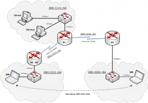
For better understanding and demonstrating of IPv6 mobility mechanisms I designed this simple but sufficient network topology. You can check it on the picture below. I used three routers to describe the mobility process, although one router with three connected networks should be also enough. However, with more routers you can easier monitor and trace the differences between direct and indirect communications with mobile node. There is connected one network switching device to every router to reflect real topology scenarios with many users in access part of the network. Also you can configure SPAN functionality (Catalyst Switched Port Analyzer) to analyze and capture the traffic flowing through.
Lower clock rate of serial link is used between the routers R1 and R3 to reflect real life scenarios, where both locations can be divided by slow WAN link. Therefore, you will also see much higher response times of mobile node when the indirect communication via Home Agent will be in place.

[click to enlarge]
Hardware:
- 3 x Cisco Router 2811 with two serial interfaces and two ethernet ports. Used IOS version: 12.4-25f (supports IPv6 and router in role of MIPv6 Home Agent)
- 3 x Cisco Catalyst 2950, 48 port switches (max. of 3 FE ports are used in this scenario)
- At least three computers running operating system with MIPv6 mobility support (check my other article to see MIPv6 support in OS)
Subnets:
- 2001:1111::/64 – home network of Correspondence Node (CN)
- 2001:2222::/64 – home network of Mobile Node (MN) , where also Home Agent (HA) router is connected
- 2001:3333::/64 – foreign network, where MN is rooming to
- 2001:4444::/64 – interconnect network between routers R1 and R2
- 2001:5555::/64 – interconnect network between routers R1 and R3
Node configuration
Router R1
hostname R1
ipv6 unicast-routing
no ip domain lookup

ipv6 router rip 1

interface FastEthernet0/0
 no ip address
 duplex auto
 speed auto
 ipv6 address 2001:1111::1/64
 ipv6 rip 1 enable
 no shutdown

interface Serial0/0/0
 no ip address
 ipv6 address 2001:5555::1/64
 clock rate 64000
 ipv6 rip 1 enable
 no shutdown

interface Serial0/0/1
 no ip address
 ipv6 address 2001:4444::1/64
 clock rate 125000
 ipv6 rip 1 enable
 no shutdown
Router R2
hostname R2
ipv6 unicast-routing
no ip domain lookup

ipv6 router rip 1

interface FastEthernet0/0
 no ip address
 duplex auto
 speed auto
 ipv6 address 2001:3333::1/64
 ipv6 rip 1 enable
 no keepalive
 no shutdown

interface FastEthernet0/1
 no ip address
 shutdown
 duplex auto
 speed auto

interface Serial0/0/0
 shutdown

interface Serial0/0/1
 no ip address
 ipv6 address 2001:4444::2/64
 ipv6 rip 1 enable
 clock rate 125000
 no shutdown
Router R3 – Home agent
hostname R3
ipv6 unicast-routing
no ipv6 cef
no ip domain lookup

ipv6 router rip 1

interface FastEthernet0/0
 no ip address
 duplex auto
 speed auto
 ipv6 address 2001:2222::1/64
 ipv6 mobile home-agent
 ipv6 rip 1 enable
 no keepalive
 no shutdown

interface Serial0/0/0
 no ip address
 ipv6 address 2001:5555::2/64
 clock rate 64000
 ipv6 rip 1 enable
 no shutdown

interface Serial0/0/1
 shutdown

ipv6 mobile home-agent
 no binding auth-option
Switches
spanning-tree portfast default
Testing
The rooming of mobile nodes between two networks 2001:2222::/64 and 2001:3333::/64 can be realized by manual reconnecting of the network cable between access switches S2 and S3. This method is sufficient for IPv6 mobility testing but you can also implement two different wireless access networks – it doesn’t matter here, we are testing Layer 3 mobility, not Layer 2 mobility.
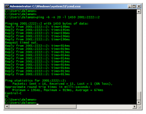
To monitor seamless network mobility I run simple ping test sending ICMP packets from CN to MN. I used higher packet payload to increase the response times. As you can see, only one ICMP request was lost during the transition between the networks !!!
Useful debug commands:
debug ipv6 mobile binding-cache
debug ipv6 mobile forwarding
debug ipv6 mobile home-agent
debug ipv6 mobile registrations
